Thermal links ( Caution to be observed when installing thermal links)
Precautions on installation of Thermal links
(1) Do not twist the body or lead wires (i.e. do not turn or rotate lead wires respect to the body).
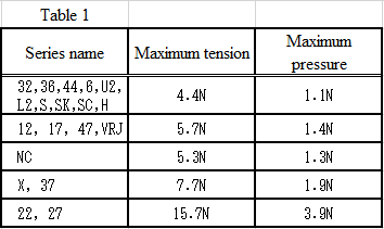
(2) Do not push lead wired toward, or pull them away from the Thermal links body at axial stresses exceeding those shown in Table 1 (room-temperature reference values). Values in Table 1 were calculated from lead wire diameter according to UL60691,EN60691.
(3) Tangential forces on the leads must be avoided (i.e. pushing or pulling on the leads at an angle to the Thermal links body) as such forces may damage the Thermal links seals.
(4) When bending a lead wire for installation, fix the part of the lead between the body and the lead section to be bent using a tool, and gently bend the lead section that is at least3 mm from the body. Never hold the body with a tool. (see Fig.2)
(5) Do not damage lead wires by holding with a sharp instrument, and do not bend at a sharp angle.
(6) After a Thermal links has been connected, do not apply excessive force that will crush the Thermal links body, sealant, or lead wires, and ensure that leads are not subjected to tension, pressing, or twisting forces with respect to the Thermal links body.

Soldering and Welding cautions
(1) Cautions to be observed when soldering and welding
(a) After soldering or welding, leave the Thermal links for at least 30 seconds to allow the sealant to cool before conducting any taping, fixing, bending, or redoing any soldering or welding. Any stress applied on the Thermal links before cooling may cause a broken wire or loss of air tightness, and this may inhibit the proper functioning of the Thermal links. If re-soldering or re-welding is done before a Thermal links has cooled, it may fuse off. Cooling time varies depending on the soldering temperature (welding conditions), soldering time, lead wire length, and other factors. To determine cooling time, conduct a test with the Thermal links that is to be used.
(b) If, after soldering or welding, the sealant is burned, or Thermal links contents have permeated out, replace with a new Thermal links even if the resistance value reads normally.
(2) Maximum permissible soldering time
(a) Using long lead wires allows for a longer soldering time. Using the longest possible leads when soldering or welding.
(b) If you must solder or weld with a short lead wire, use a heat sink between the soldering or welding point and the sealant. Users should conduct tests for each application, and individually determine the soldering time that will not adversely affect the Thermal links.
(3) Connecting Cautions
When connecting leads by welding or crimping, measure the electrical resistance of the connection with a low-range ohmmeter, and always ensure that you have a good connection with low resistance. If resistance is high, this could bring about a malfunction due to heating, or cause the Thermal links temperature to exceed the maximum use temperature. Perform sampling inspections to make sure that connections have sufficient mechanical strength.
Application guidance
- ELCUT THERMAL LINKS INSTRUCTION MANUAL
- ELCUT THERMOPROTECTOR ETR INSTRUCTION MANUAL
- ELCUT THERMOPROTECTOR WITH RESISTOR EC INSTRUCTION MANUAL
- ELCUT THERMOPROTECTOR TR4L INSTRUCTION MANUAL
- ELCUT THERMOPROTECTOR TR6L INSTRUCTION MANUAL
- Thermal links/resistor assemblies (Caution)
- Thermal links/resistor assemblies (Caution to be observed when designing for use of thermal links)
- Thermal links/resistor assemblies (Caution to be observed when installing thermal links)
- Thermal links/resistor assemblies (Other caution)
- Thermoprotector with resistor (Caution to be observed when installing thermal links)
- Thermoprotector with resistor (Caution to be observed when designing for use of thermal links)
- Thermoprotector with resistor (Other caution)
- The Fusing Resistor BZ05 (Caution to be observed when designing)
- BZ05 (Caution to be observed when installing)
- BZ05 (Other caution)
- The Fusing Resistor BZ07 (Caution to be observed when designing)
- BZ07 (Caution to be observed when installing)
- BZ07 (Other caution)
- ELCUT Thermal links/resistor assemblies INSTRUCTION MANUAL
- Thermal links ( Caution)
- Thermal links ( Caution to be observed when designing for use of thermal links)
- Thermal links ( Caution to be observed when installing thermal links)
- Thermal links (Other caution)
